
Introduction
I’ve been working on a Material Function Library for 2D Sign Distance Field that contains shapes and relative merging and manipulating operations.
I think it’s very useful and valuable knowledge for any Technical or Environment Artist, but really for anyone that works with materials.
There will be a few posts about this topic, in this first one, I will show how to make some simple shapes and explain the basics to visualize them.
I will then cover different ways to combine these shapes, more advanced techniques to manipulate them and then how you can use distance fields to create gradients and flow maps.
Everything I will cover is not new knowledge, I’ve learned most of it by reading Ronja and Inigo Quilez’s articles which I highly recommend for getting a better understanding.
The focus of my posts is to show how their content can be recreated in Unreal Engine, as well as share some extra tips I’ve learned along the way.
I’m sorry in advance if these posts will be long, but I think they are worth reading, enjoy!!
Basic Shapes
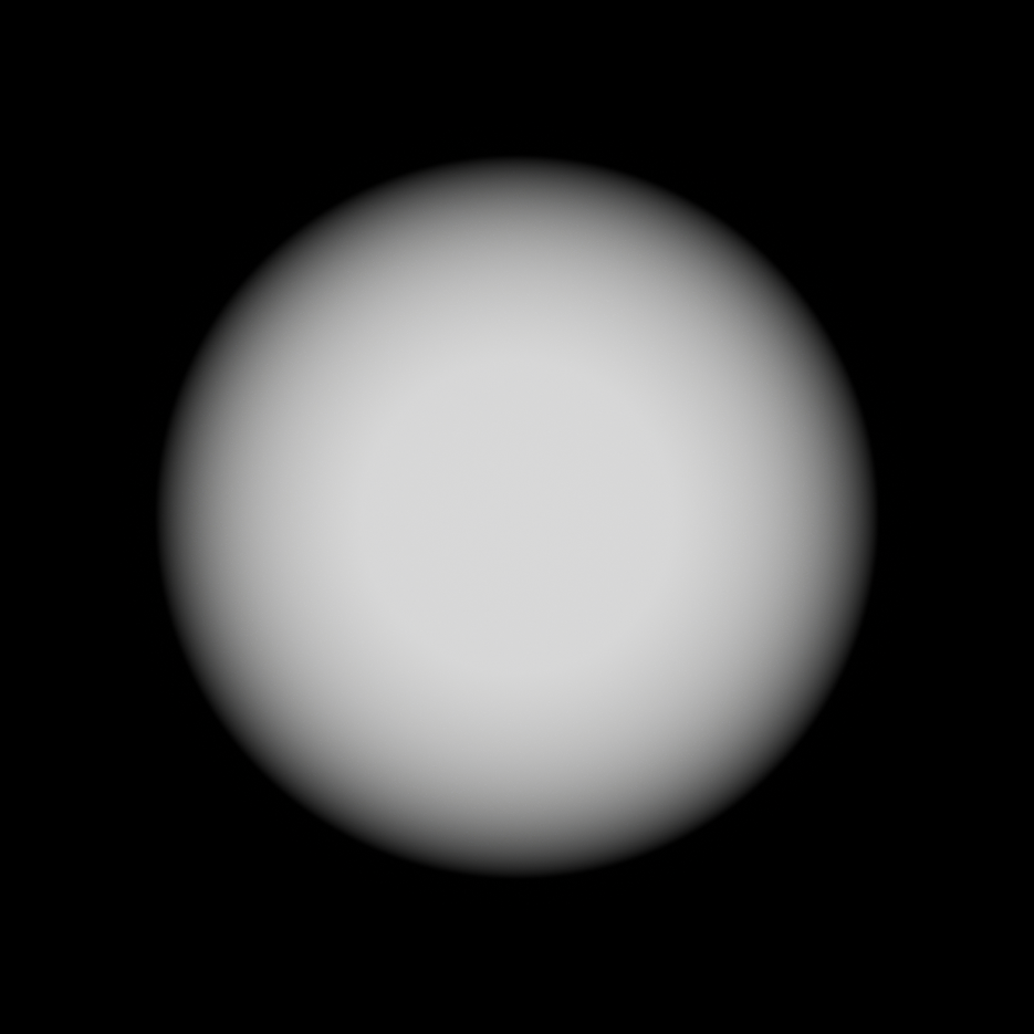
Let’s start with some basic shapes, the screenshots and gifs you will see below are using a function I made that helps visualize distance fields.
For now, all you need to know is that the thicker white line represents the SDF shape, red is for the inside, and light blue is for what’s outside of the shape.
One thing that all the shape functions share is that they require a Position input, to keep things simple I’m just using the UVs and then visualize the result on a simple plane. To center them I just subtract 0.5 from the UVs, I didn’t include the subtraction node in the functions themselves so that they are more versatile and can be used, for example, with Wolrd Position values.
Circle
This is for sure the easiest distance field function:
float circle(float2 Position, float Radius)
{
   return length(Position) - Radius;
}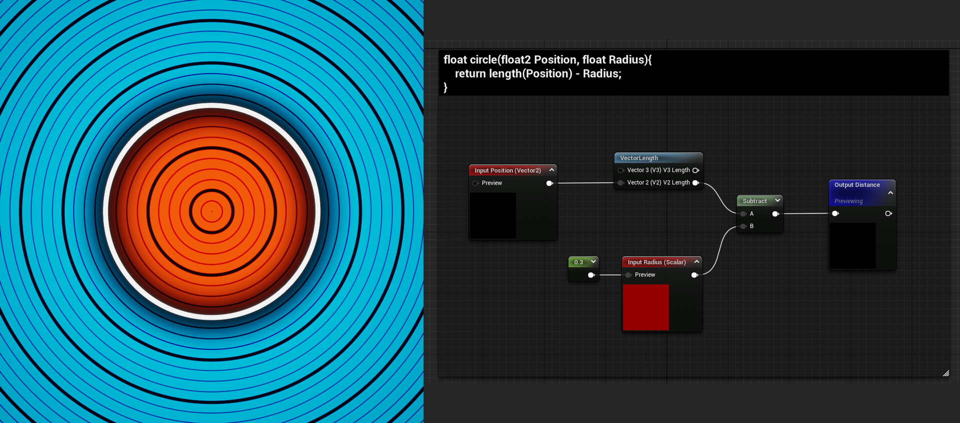
The size of the circle can be controlled with the Radius parameter.
Rectangle
Here’s the rectangle’s function:
float rectangle(float2 Position, float2 Size)
{
    float halfSize = Size * 0.5;
    float2 d = abs(Position) - halfSize;
    float outsideDistance = length(max(d, 0));
    float insideDistance = min(max(d.x, d.y), 0);
    return outsideDistance + insideDistance;
}
Size can be controlled with a vector2, this allows independent control on the 2 axes or just input the same value for both to get a square.
Triangle
The triangle’s a little bit more complicated:
float EquilateralTriangle(  in vec2 p, in float r )
{
    const float k = sqrt(3.0);
    p.x = abs(p.x) - r;
    p.y = p.y + r/k;
    if( p.x+k*p.y > 0.0 ) p=vec2(p.x-k*p.y, -k*p.x-p.y) / 2.0;
    p.x = p.x - clamp( p.x, -2.0*r, 0.0 );
    return -length(p) * sign(p.y);
}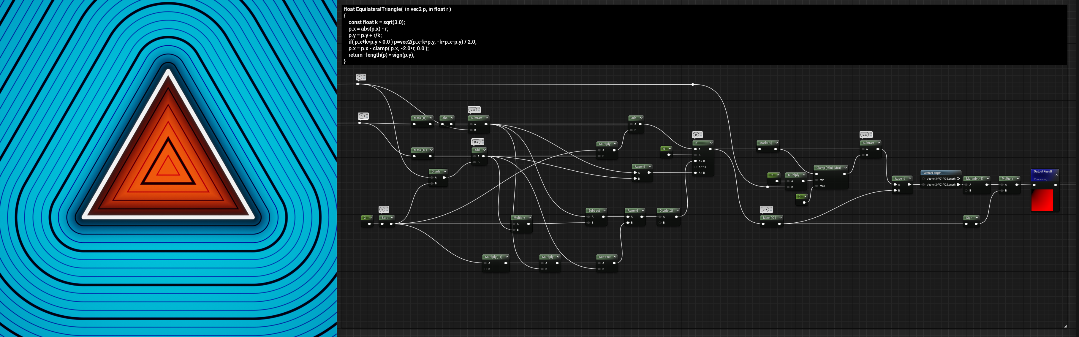
Similar to the circle, the size can be controlled with a single float.
Segment
The segment’s also another very useful shape:
float Segment( in vec2 p, in vec2 a, in vec2 b )
{
    vec2 pa = p-a, ba = b-a;
    float h = clamp( dot(pa,ba)/dot(ba,ba), 0.0, 1.0 );
    return length( pa - ba*h );
}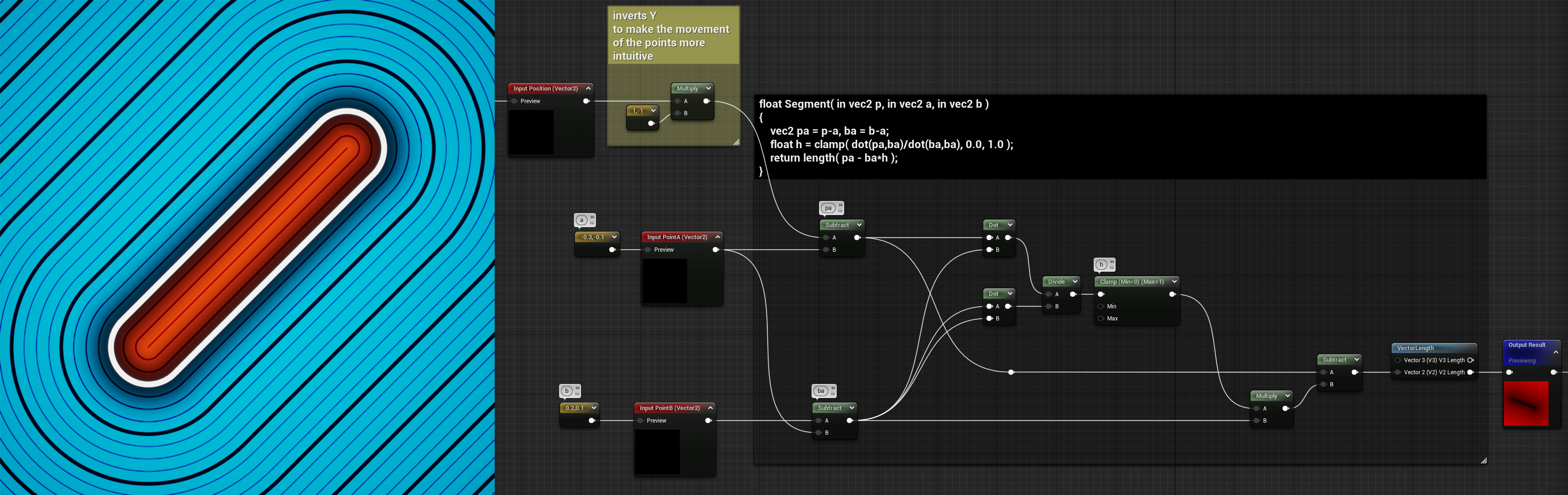
This function actually draws a line between two points, so the inputs are two vector2 parameters, and each vector2 defines the location of one of the points.
Regarding the thickness of the line, it’s not defined by an input but it can still be adjusted by using another technique explained below.
Rounded Corners
Each point in a distance field only stores one value: the distance to the closest point of the perimeter of the shape we’re representing. You probably noticed on the images and video shown above that the lines “outside” of the shapes are getting rounder and rounder the further away they are from the shape perimeter. If you go far enough any distance field becomes a perfect circle.
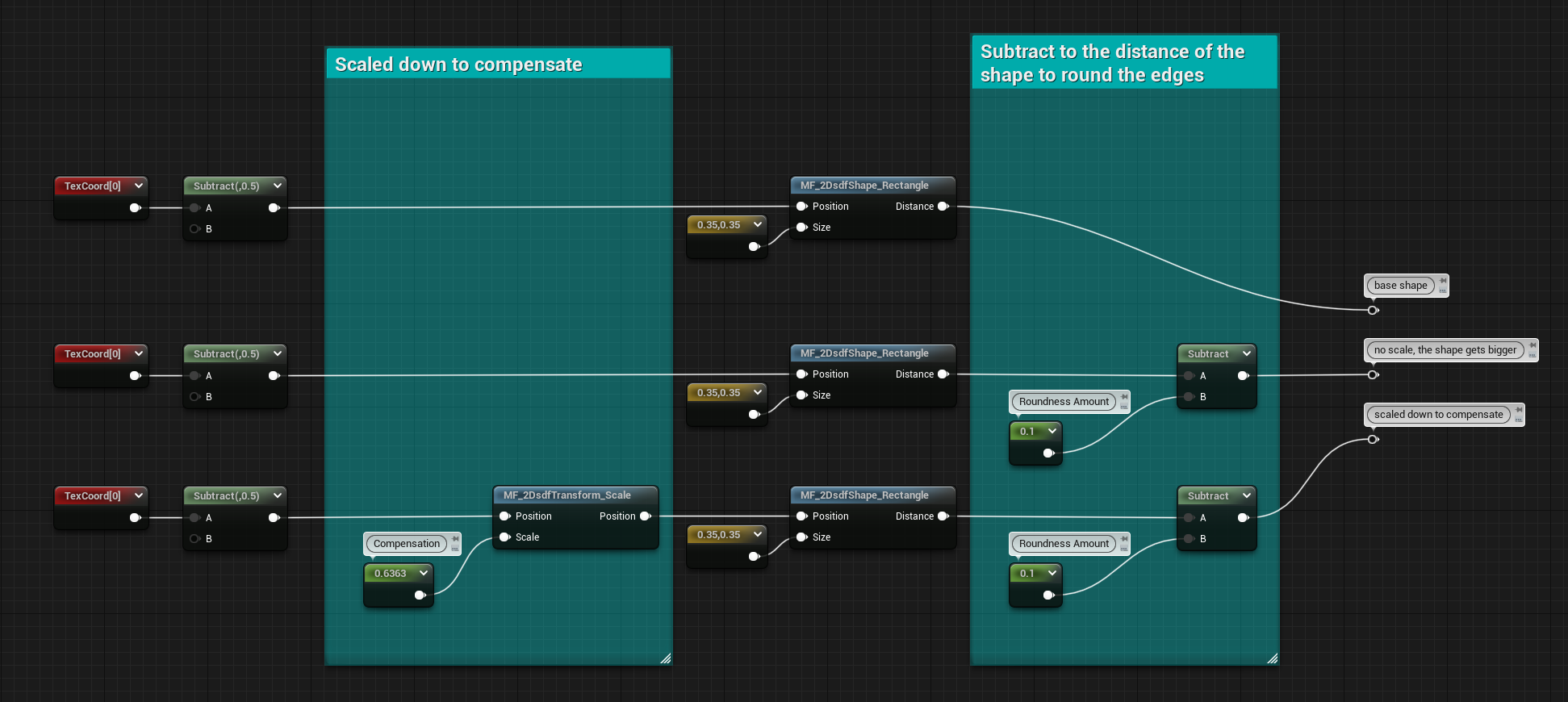
This can be used to our advantage, subtracting a value to the SDF before visualizing it will round the edges of any shape, this is also how I changed the thickness of the Segment shape earlier.
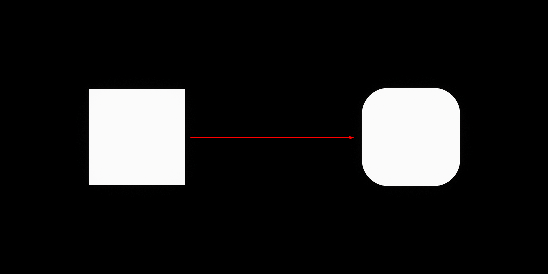
The only thing you need to be aware of when doing this is that in the process of rounding the edges the shape also changes in size and becomes bigger since now to visualize the shape we’re essentially using points further away from the original perimeter.
So, you will have to scale it down if you wanted the shape to remain of the previous size. I’ll cover both visualization and scaling methods later in the post.
The following graph and the video shows an example of a square SDF in both its original and rounded state, trying to keep them both the same size.
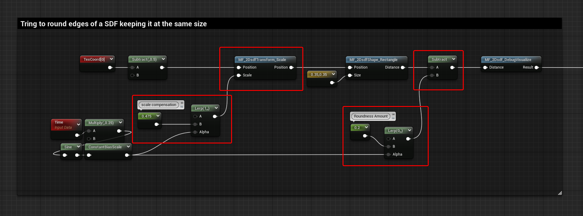
Here’s a comparison of the graphs:
- Basic Shape
- Rounded Edges
- Rounded Edges with Scale Compensation
Basic Visualisation Methods
I would say there are 3 basic methods to visualize sign distance fields, which involve Step, Smooth Step, and Linear Step functions.
If you want to learn more about them you can check out one of my previous blog posts where you can find more information about them.
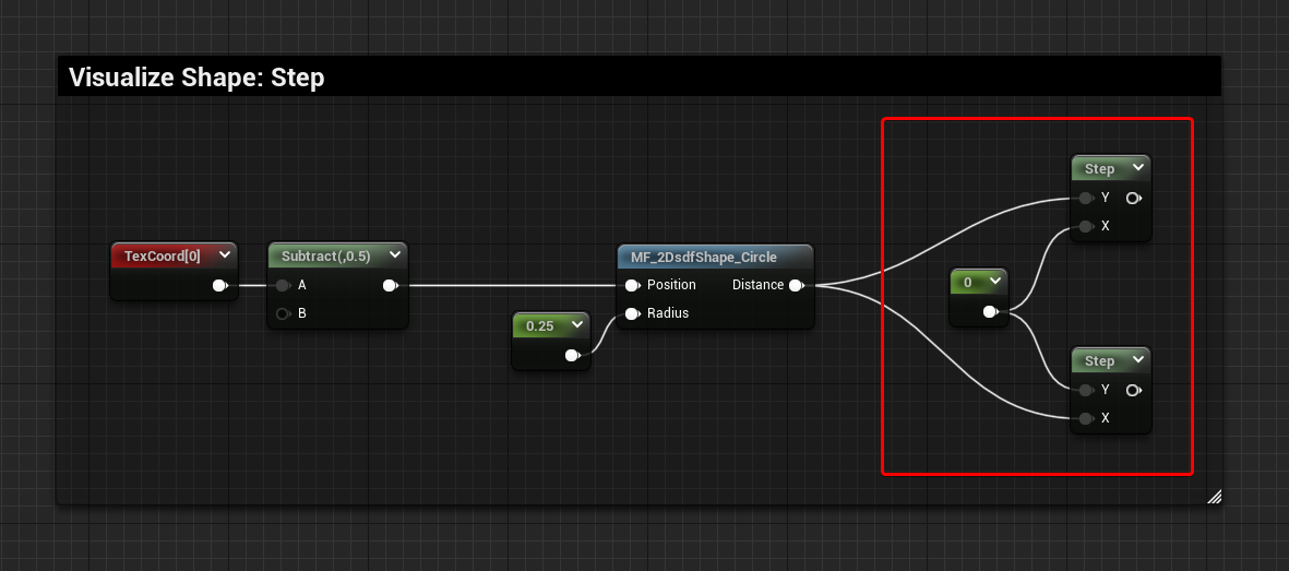
Step
The most straightforward and basic way to visualize a distance field.
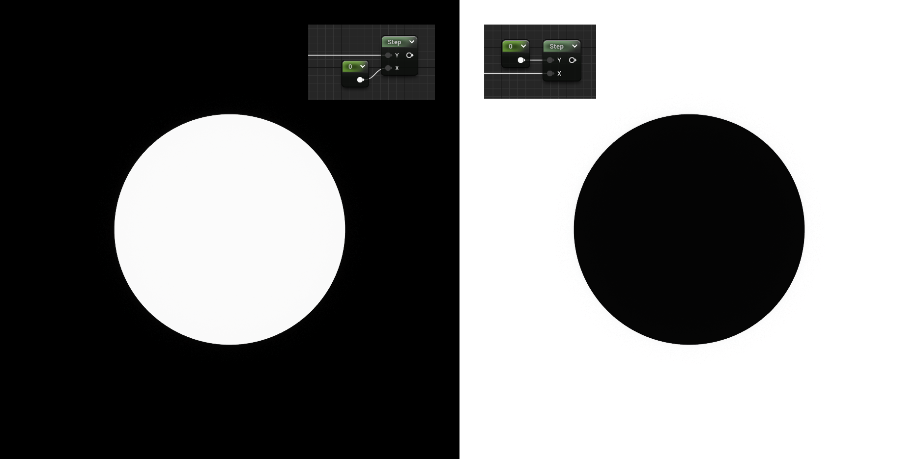
Simply drop a step node, and use the SDF as the first input and a value of 0 as the second input. If you want to invert the inside and outside of the shape, just invert the two inputs.
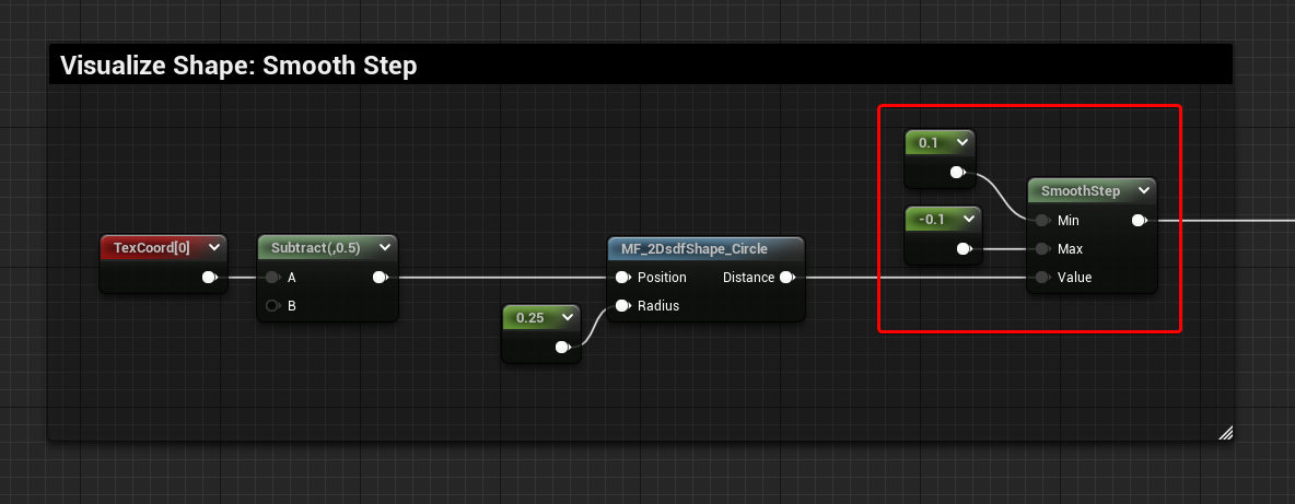
Smooth Step
The Smooth Step it’s probably the function I use the most to visualize SDF because It creates a nice gradient and you can define its start and end position.
Similar to the Step function, you can invert the Min and Max value to invert the inside and outside of the shape.
The example below shows a Min value of 0.1 and a Max value of -0.1. This makes the gradient start where values are -0.1 in the SDF, which are inside the perimeter of the shape, and it ends where the values are 0.1, just outside of the perimeter.

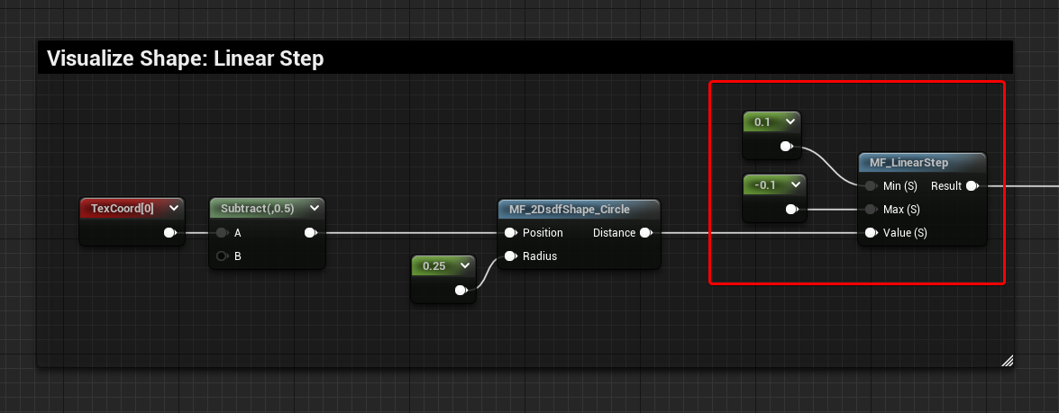
Linear Step
The unwanted and a little bit ugly brother, it’s exactly the same as the Smooth Step function, the only difference is that the interpolation is linear instead of smooth. I’ve never really found it very useful, but I wanted to mention it there since it might be a good option in some specific cases.
Of course, there isn’t a built-in node for it in Unreal’s Material Graph, so you will have to make your own function, again, more about it here.
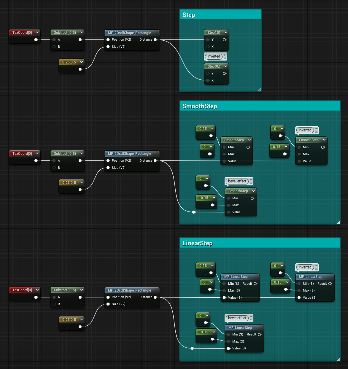
The screenshot below gathers all methods in one image.
Using values inside the perimeter of the shape for the Smooth Step and Linear Step functions also gives an interesting result, something similar to a bevel node in Substance Designer.

Animate Shapes
As you noticed in the videos above, the shapes can be animated. That can be easily done just by animating the parameters using time nodes and sine and cosine functions, the shapes will automatically update.
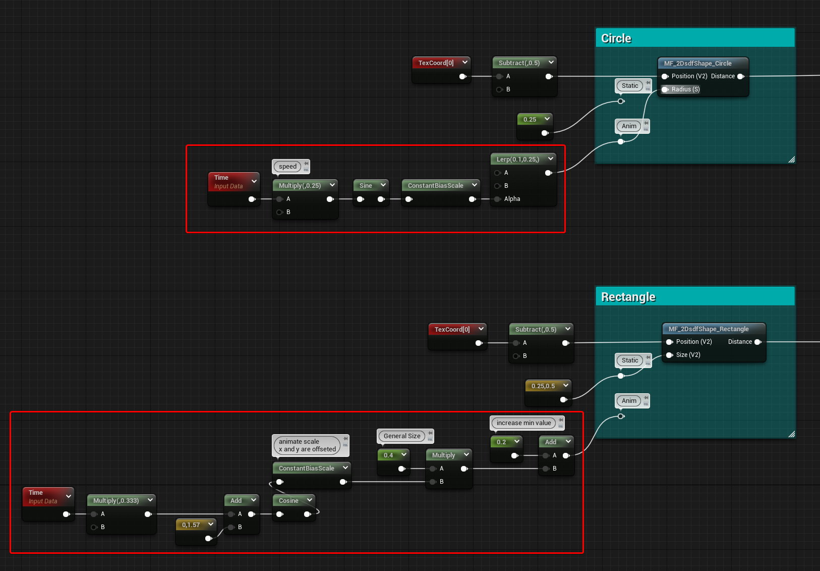
Below you can see a couple of examples.
For the Circle I’m using a Sine node and ConstantBiasScale to remap the value between 0 to 1, then I just used the result as the Alpha value for a Lerp, this way I can easily control the min and max value of the animation. Time is also multiplied by a float to control the speed.
In the Rectangle example, since it needs a vector2 and I wanted the animation of the 2 values to have an offset I’ve added an arbitrary value to one of the two and then did the same as before, but using a cosine instead of sine. Because the output it’s a vector2 I can’t use it directly as an Alpha for a lerp to do control the animation, so instead, I remapped the values using a multiply and an add node, essentially creating a “ConstantScaleBias” having the multiply control the overall size and the addition node to offset the animation away from 0 (different from BiasScale since the two operations are swapped). Again, Time is multiplied by a float to control speed.
Annular Shapes
SDF can be visualized in a way that gives annular shapes.
All the values outside of a shape are positive, while the ones inside its perimeter are negative.
This means that if we absolute the SDF so that we only have positive values we’re left only with the perimeter of the shape, where the values are 0. If we then subtract from it we can make all the values near the perimeter negative, creating annular shapes. The subtraction amount controls the thickness of the shape.
Waves Patterns
The SDF can be used to create some interesting wave patterns, I’ll cover them now.
Frequency can be controlled by multiplying the SDF. In all the examples, I’m also adding time to animate them.
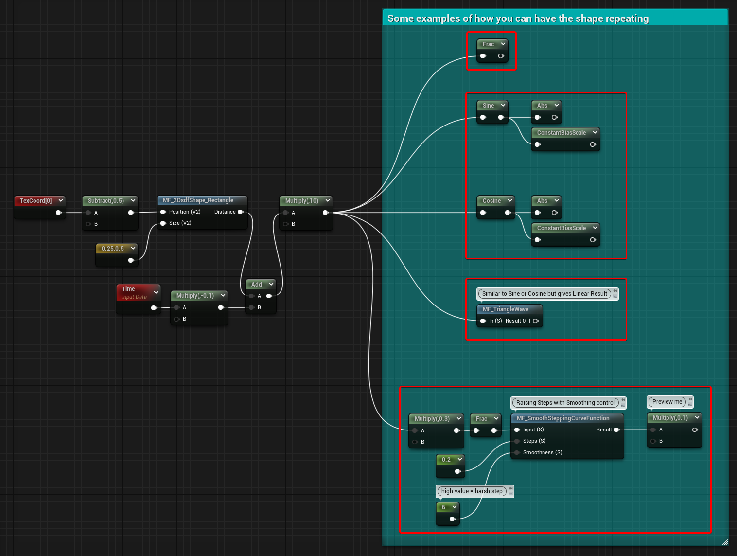
Frac
Returns the fraction part of the SDF. You should get the same result using a % node and value of 1 for the second input.
Sine and Cosine
Of course, they both give basically the same result, the output will be a gradient that goes between -1 and 1, if you want only positive values you can try an abs or ConstantBiasScale node.
Triangle Wave
Very similar to the previous example, but it returns a linear gradient.
Check out one of my previous posts about it.
In the example below the gradient goes from 0 to 1.
Smooth Stepping Curve
I tried to experiment with this function as well.
You can find more about it here to use it in Unreal Engine, and here if you’re interested in it for remapping noises in Substance Designer.
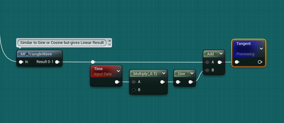
Other – Tangent
I wanted to share a couple of more interesting findings using tangent nodes.
The first one is just using the tangent after a ConstBiasScale of a Sine node:
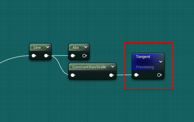
The second one is a little bit more trippy, this is the setup:
Advanced Visualisation
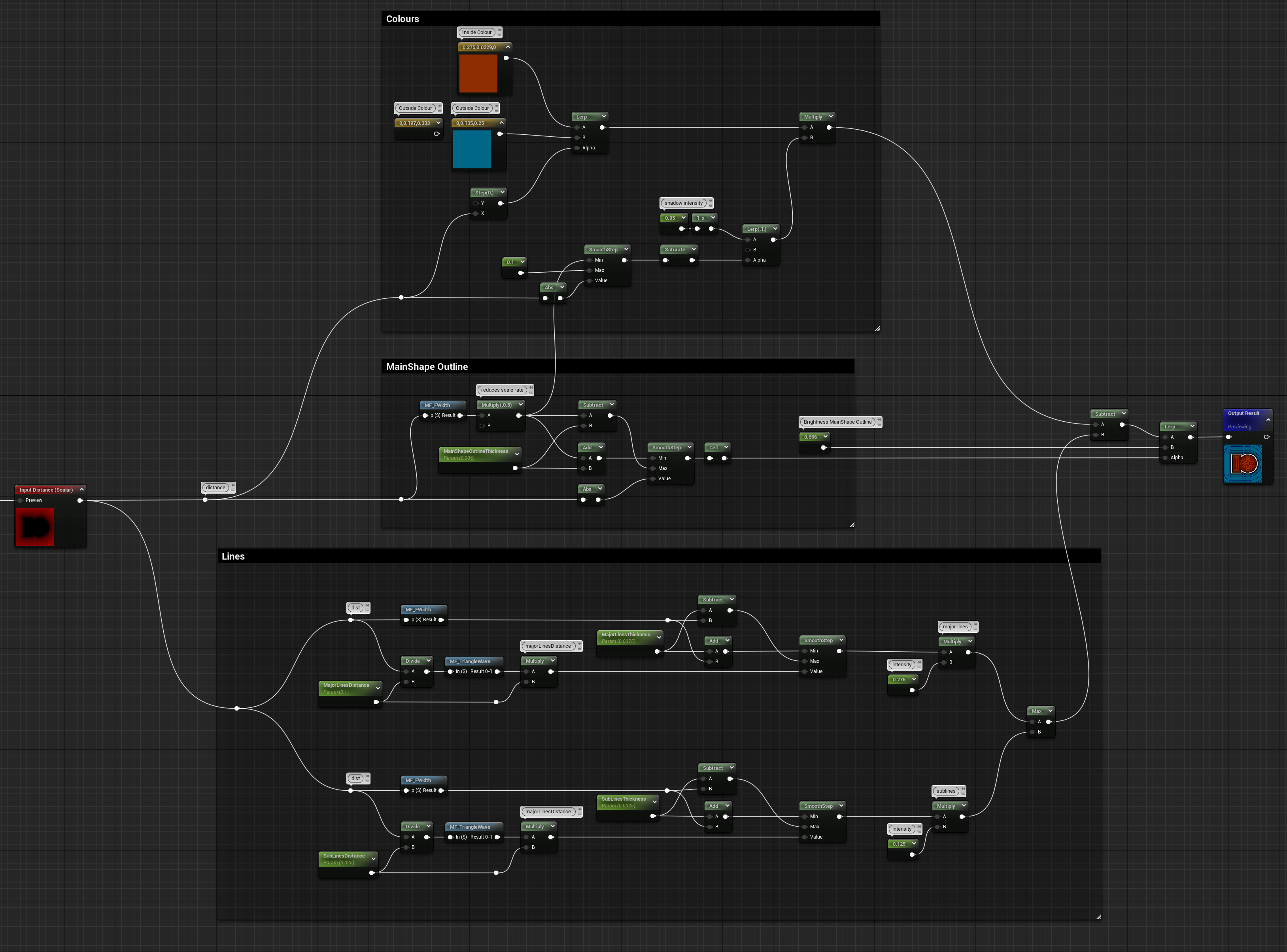
If you’ve read everything up until here you are now ready to create your own custom advanced visualizer like the one you saw earlier.
You can use positive and negative values to colour the inside and outside of the shape, use the annular technique to visualize its perimeter, wave patterns to show the outer and inner space distances and use Smooth Step functions to create some nice subtle shadow gradients.
Here you can find the snippet of the one I made, but I highly recommend you try and make your own one, it’s a fun challenge!
Basic Transformations
One last thing I wanted to cover in this post is how SDF can be manipulated using basic transformations such as offset, rotate and scale.
The way this is done is by transforming the position values that are fed in the SDF Shapes functions.
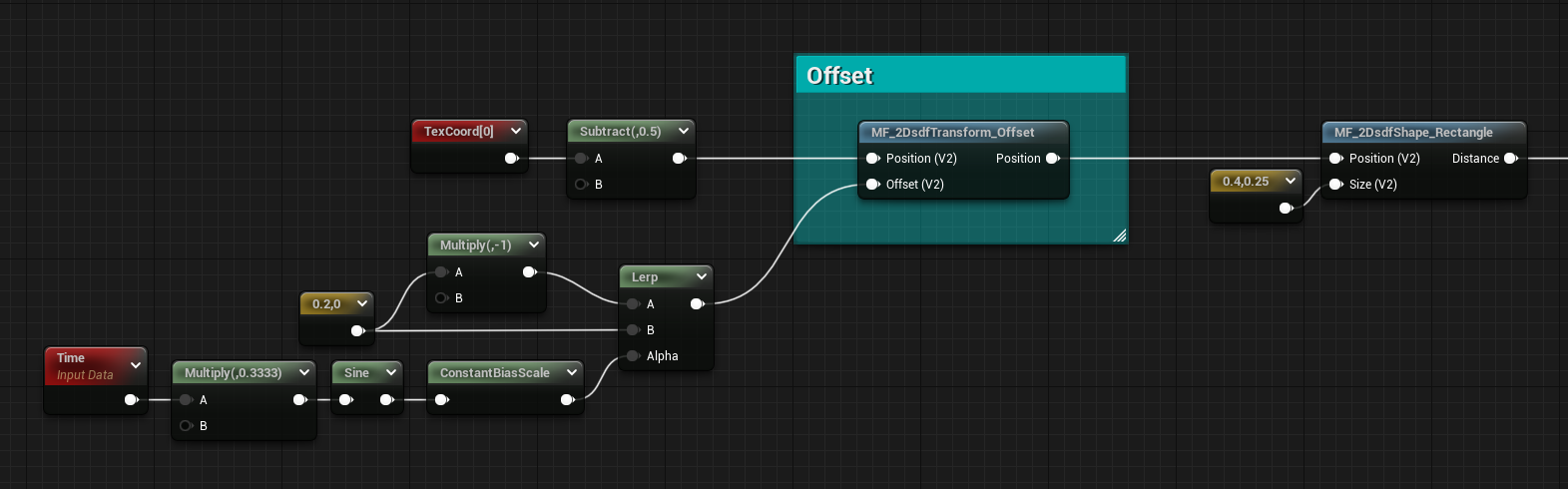
Offset
The offset is quite simple, just subtract from the Position. We’re not doing an addition because we are manipulating the space. If we move the space towards a direction, the shape we draw into it will move the opposite way.
float2 translate(float2 Position, float2 Offset)
{
    return Position - Offset;
}
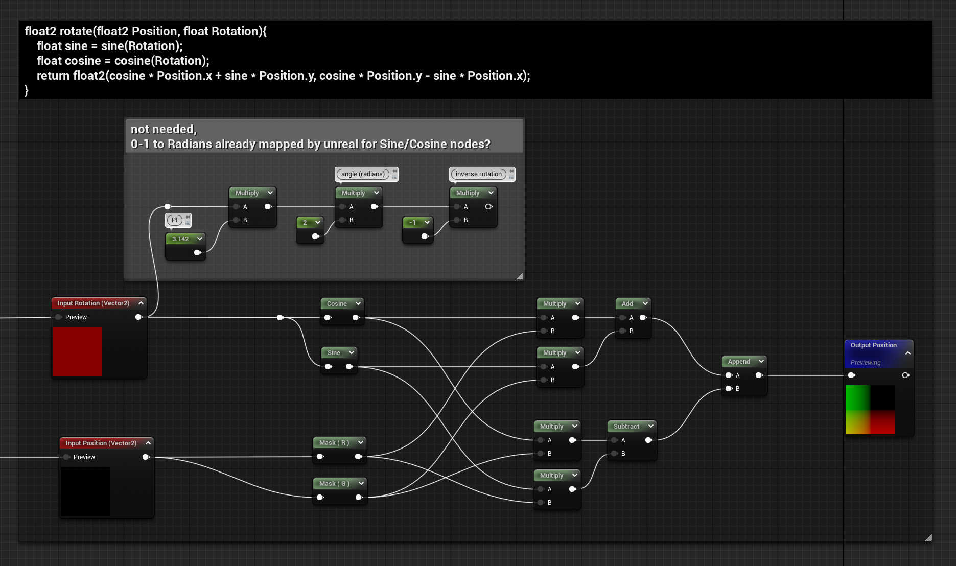
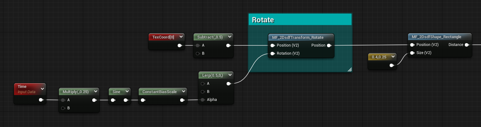
Rotate
The rotation’s definitely worth having inside a function, unlike offset and scale.
I noticed some weird behavior from both the Sine and Cosine nodes in Unreal, they don’t output the same value sin() and cos() do in hlsl. To get the same result you need to divide the input of the nodes by 2pie. I think this was done to make the nodes give better out-of-the-box results when TexCoord and Time nodes are plugged in as the input.
So unlike Ronja, to have the rotation being from a 0 to 1 value I didn’t have to remap it to radiants. I found this very interesting since this affects any rotational math done in the material graph, so I’ve left the nodes inside a comment for future reference.
float2 rotate(float2 Position, float Rotation)
{
    float sine = sine(Rotation);
    float cosine = cosine(Rotation);
    return float2(cosine * Position.x + sine * Position.y, cosine * Position.y - sine * Position.x);
}
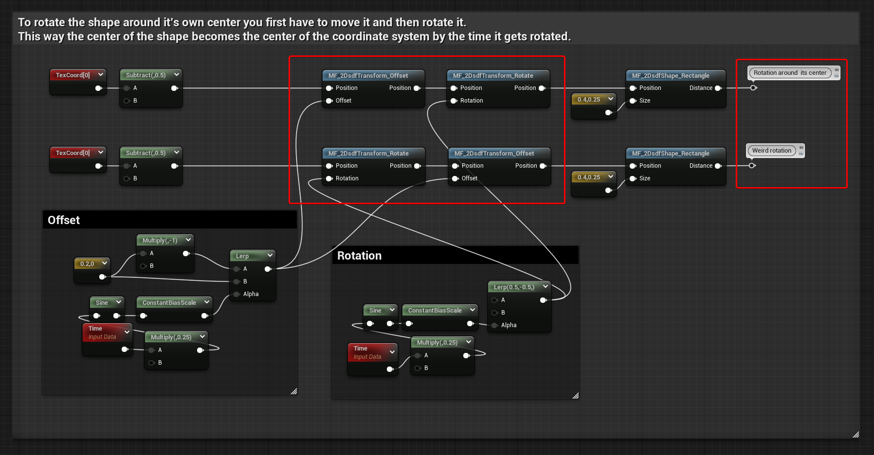
Another thing to mention is that if you’re using both Rotate and Offset functions, the order you use them gives different results. If you want the shape to always rotate at its own center the Rotate function should be used after the Offset one.
Below you can find a comparison, when the rotation is done before the offset the result it’s weird, but might be desired in some cases.
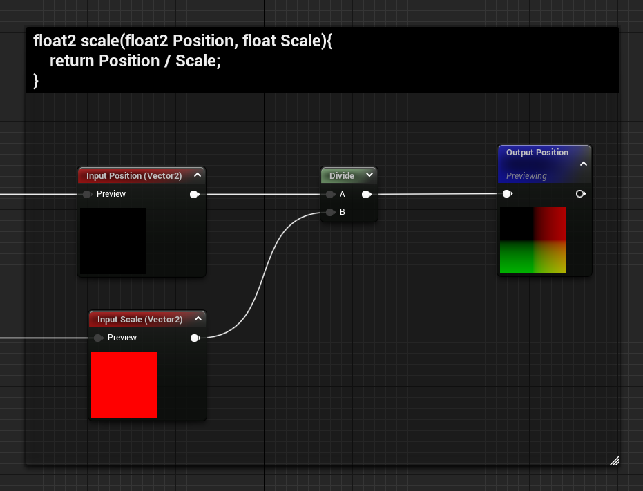
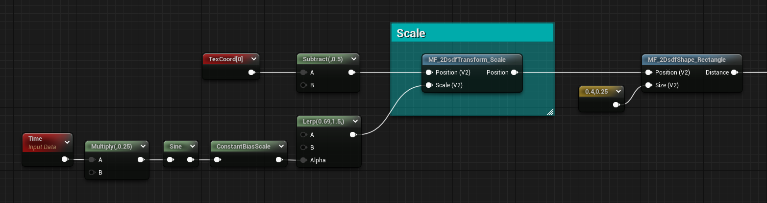
Scale
You might find this a little bit useless since most of the SDF Shapes functions I showed you at the start of this post have already controls for their size. However, when you have multiple of them and start using some merging functions this is a quick way to rescale them all at the same time.
The function’s simple, get the position and divide it by the scale.
float2 scale(float2 Position, float Scale)
{
    return Position / Scale;
}
Conclusion
If you didn’t realize it yet, I fell in love with distance fields and I hope you can now see their potential as well!!
However, if that’s not the case and you’re still resisting their magnificent charm, don’t worry, there will be a few more posts about them that will cover more advanced techniques!
I know this post was quite long, but I really appreciate you’ve read the entirety of it!!
(Eheh yes, I’m looking at you scroller, you should feel ashamed, go back up and look at all the pretty pictures at least!!)
Jokes aside, thanks a lot, I hope I managed to teach you something new, have a good rest of the day!
Leave a Reply