Introduction
In this blog post, I’ll go over how you can sample a texture in HLSL, more specifically, in a Custom Node Material Graph of Unreal Engine.
I won’t be only showing the code itself, but how you can find it out on your own, as well as doing a little breakdown of the function that is used, and how you can take the investigation further.
Investigate Compiled Code
You can see how a texture is sampled by comparing the compiled code of an empty Graph with one that has a texture.
| Window
	↳ Shader
		↳ HLSL Code
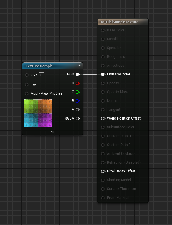
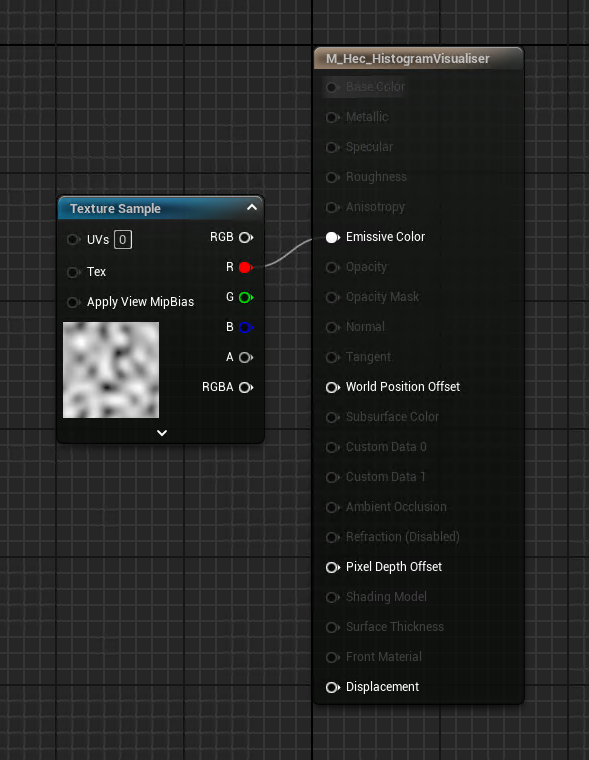
Below, you can see a comparison of the compiled code for an empty material and one with the Default Texture plugged into the Emissive Channel, both using an Unlit shading model.
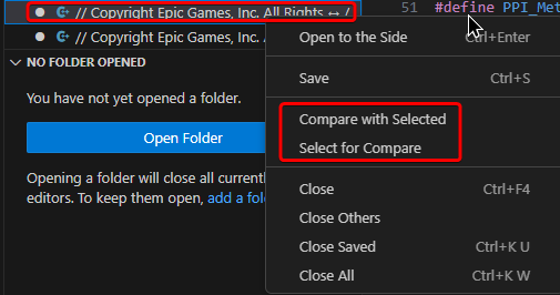
You can do the comparison in Visual Studio Code by right-clicking the file and selecting Compare with Selected on one file, and Select for Compare on the other.
These are the differences:


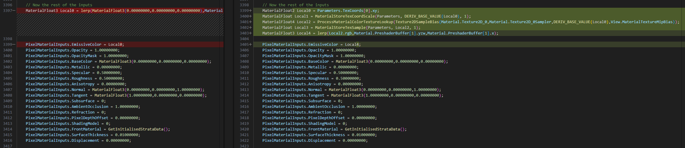
(The code in the last image it’s actually repeated twice)
You can see the texture is sampled with the following code:
MaterialFloat2 Local0 = Parameters.TexCoords[0].xy;
MaterialFloat4 Local2 = ProcessMaterialColorTextureLookup(Texture2DSampleBias(Material.Texture2D_0, Material.Texture2D_0Sampler, DERIV_BASE_VALUE(Local0), View.MaterialTextureMipBias));Custom Node
Update the Code
Let’s take that and adapt it so that we can drop it in a Material Graph Custom node.
There are a couple of things to be done:
- Rename Variable and Return it → Rename the
MaterialFloat4variable to something else, likesampledTex. This way, we can use it as the output of the function, addingreturn sampledTex;at the end. - The Texture Parameter → This needs to be exposed as an input, which can be done by replacing
Material.Texture2D_0with the name of the input Parameter, I chosetexObject. - UV → The texture sampler requires UV to sample the texture. In the compiled shader, you can see that
TexCoords[0]is fetched using the variableLocal0. You can keep it as is, but the Custom node will complain about not having access to TexCoord[0] Parameter, which means you still need to plug the TexCoord node in the Custom node, might as well expose it properly, this way, we can manipulate them outside of the custom node. Rename Local0 with something clearer, I chosemyUv. Then, replaceParameters.TexCoods[0].xywith the name of the exposed input parameter, I went withuv. - Simplify MaterialFloat → You can rename
MaterialFloatwith justfloat. This is not necessary, but I don’t think it has any implication in doing so.
Below you can see the updated code:
float2 myUv = uv;
float4 sampledTex = ProcessMaterialColorTextureLookup(Texture2DSampleBias(texObject, texObjectSampler, DERIV_BASE_VALUE(myUv), View.MaterialTextureMipBias));
return sampledTex;Node Graph Implementation
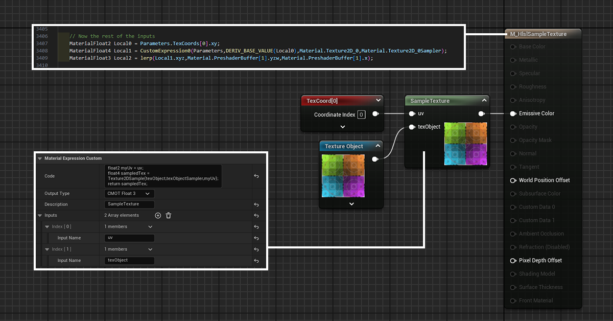
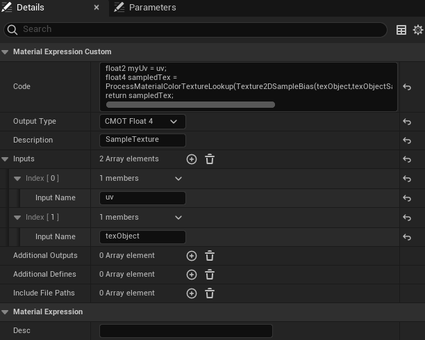
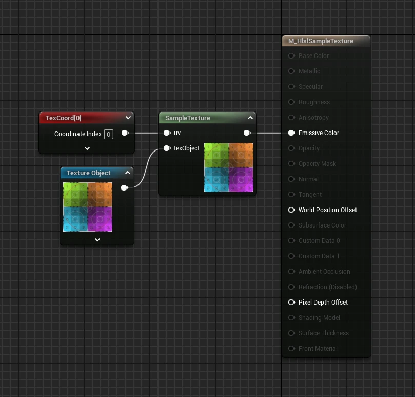
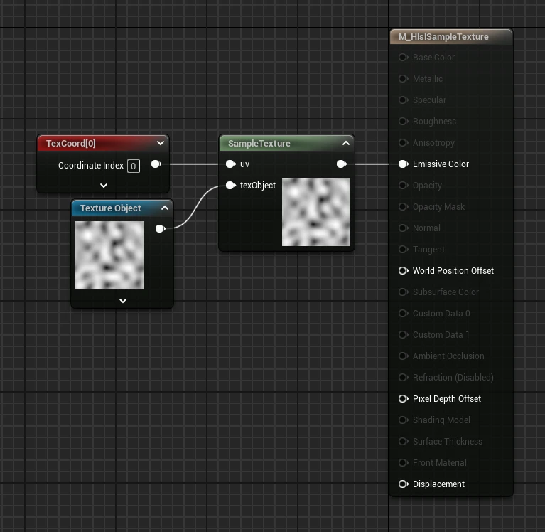
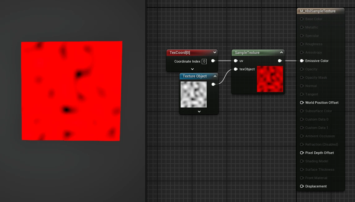
Now the code can be implemented in the Material Graph by using the Custom node.
Rename the node, paste the code in it, add the inputs for the exposed parameters uv and texObject, and plug your desired texture and UVs into the exposed pins.
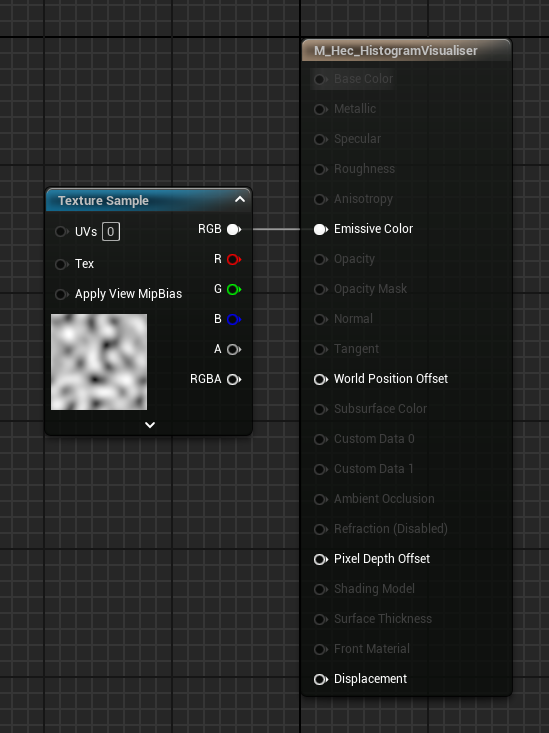
Compare Compiled Code
Now let’s save the compiled HLSL code and do a comparison with the previously compiled code, the one in which there was a Texture Sample plugged in the Material Attributes.
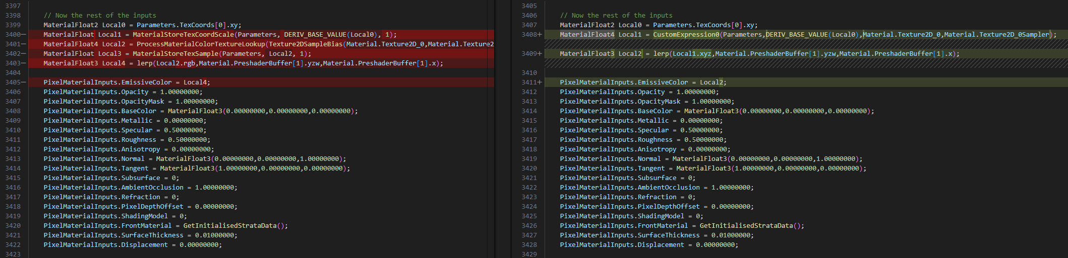
The first thing that can be noticed is that under // Uniform material expression we can now see the code that was placed inside our custom node, called CustomExpression0, which outputs a float4:

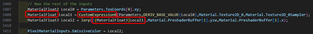
Scrolling down, under // Now the rest of the inputs there is the CustomEpxression0 getting called to calculate the EmissiveColor, instead of the Texture Sampling that was there before:
Further Breakdown
Texture Lookup
Linear Greyscale
ProcessMaterialColorTextureLookup() is used to set the Sample Type to use the Color option, however you can change it based on the texture you are sampling.
For example, you could use ProcessMaterialLinearGreyscaleTextureLookup() to sample a texture with the “Compression Settings” set to Grayscale (G8/16, RGB8 sRGB).
(I find it hilarious that both the “Compression Settings” and the “Sampler Type” labels use the American spelling “gray”, while the HLSL code uses the British English “grey”. Don’t misspell the HLSL code, or it won’t compile!)
This can be simply checked by plugging in your desired texture and look at the compiled code, the same can be done with any other “Sampler Type”.

What’s interesting to take notice of here is that the variable Local2 remains a Float4.
Colour Channels
So, what happens if we use one of the 3 channels instead of the packed RGB output?
The Texture still gets sampled as a Float4, then the Float3 variable called Local4 makes a Float3 value by fetching only the targeted channel, which then gets used for the EmissiveColor:

If you change the channel to Green, it compiles into (MaterialFloat3)Local2.g instead of (MaterialFloat3)Local2.r.
Why does it not store the sampled texture as a scalar Float, if it knows that we are using a Linear Grayscale texture?
I might be wrong, but I believe it doesn’t because otherwise the Material Graph’s Texture Sample node’s UI would need to be updated, to hide all the output pins you shouldn’t be using.
By assuming all textures contain 4 channels, the UI doesn’t need to be dynamically updated based on the node’s settings, and instead, the Texture Lookup handles the output of the sampled texture (a little bit more about this in the next section).
Now let’s try a custom node with some different combinations, replacing the Lookup to Linear Greyscale for all of them:
- sampledTex as float4 and Output Type set to CMOT Float 4
When changing only the Lookup and keeping both the sampler and the custom node output to float 4, the compiled result will be very similar to what we just saw above: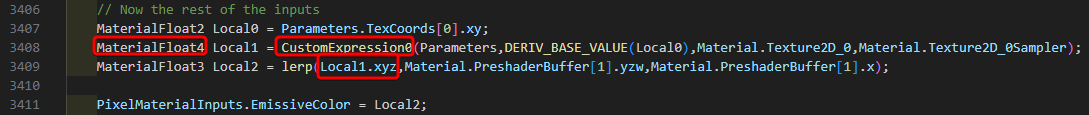
- sampledTex as float4 and Output Type set to CMOT Float 1
When changing the custom node output Type to float 1 we can observe that both the CustomExpression0 and the Local1 variable update accordingly, and Local2 behaves exactly like the example in which we selected only one channel of the Texture Sample, converting the scalar float value to float3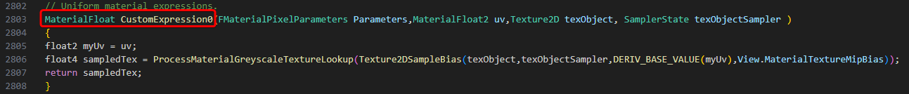
- sampledTex as float and Output Type set to CMOT Float 1
Then, if we know we are using a greyscale texture, do we need to store the sampled values in a float4? Nope, you can simply store it as a scalar float; the result will be the same.
Is there any reason to do this? I couldn’t find any, other than knowing how you are storing the data in the custom node and how it flows from one place to another, at least until I tried to remove the Lookup Texture!
Remove Lookup Texture
The texture can also be sampled by removing ProcessMaterialColorTextureLookup() and only using Texture2DSampleBias().
float2 myUv = uv;
float4 sampledTex = Texture2DSampleBias(texObject,texObjectSampler, DERIV_BASE_VALUE(myUv), View.MaterialTextureMipBias);
return sampledTex;While testing this with a greyscale texture, the material resulted in the colour red:
To get around this, you need to change either the sampled texture variable or the “Output Type” of the custom node from float4 to a scalar float.
I think this supports what I mentioned earlier. Unreal HLSL code compiles in a way which assumes all textures contain 4 channels; this way, texture controls can be easily exposed to the users in the Material Graph, then the Texture Lookup handles the output of the sampled texture so that the final result is what the user expects.
When selecting a texture to use in a Texture Sample node, Unreal automatically assigns the Sampler Type based on the texture’s Compression Settings. If you change the Sampler Type to the “wrong one”, Unreal doesn’t even allow you to compile the shader, not because there is an error in the code, but because it’s preventing you from getting an undesired result.
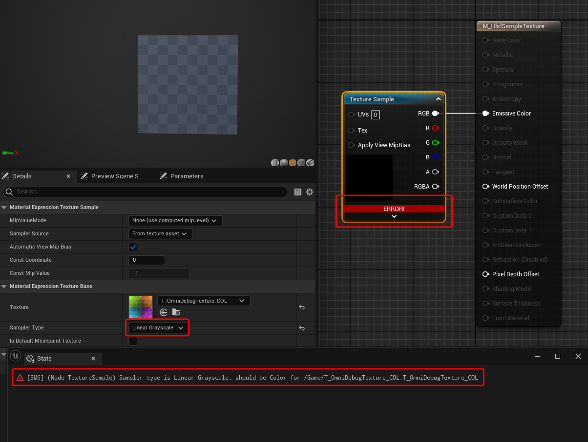
This can be easily tested by exposing a Texture Sample node to a parameter, then making a Material Instance and selecting a texture that should be using a different Sampler Type.
In the example below, I’ve set up the material to use a Color texture, and then used a Linear Grayscale texture in the Material Instance.
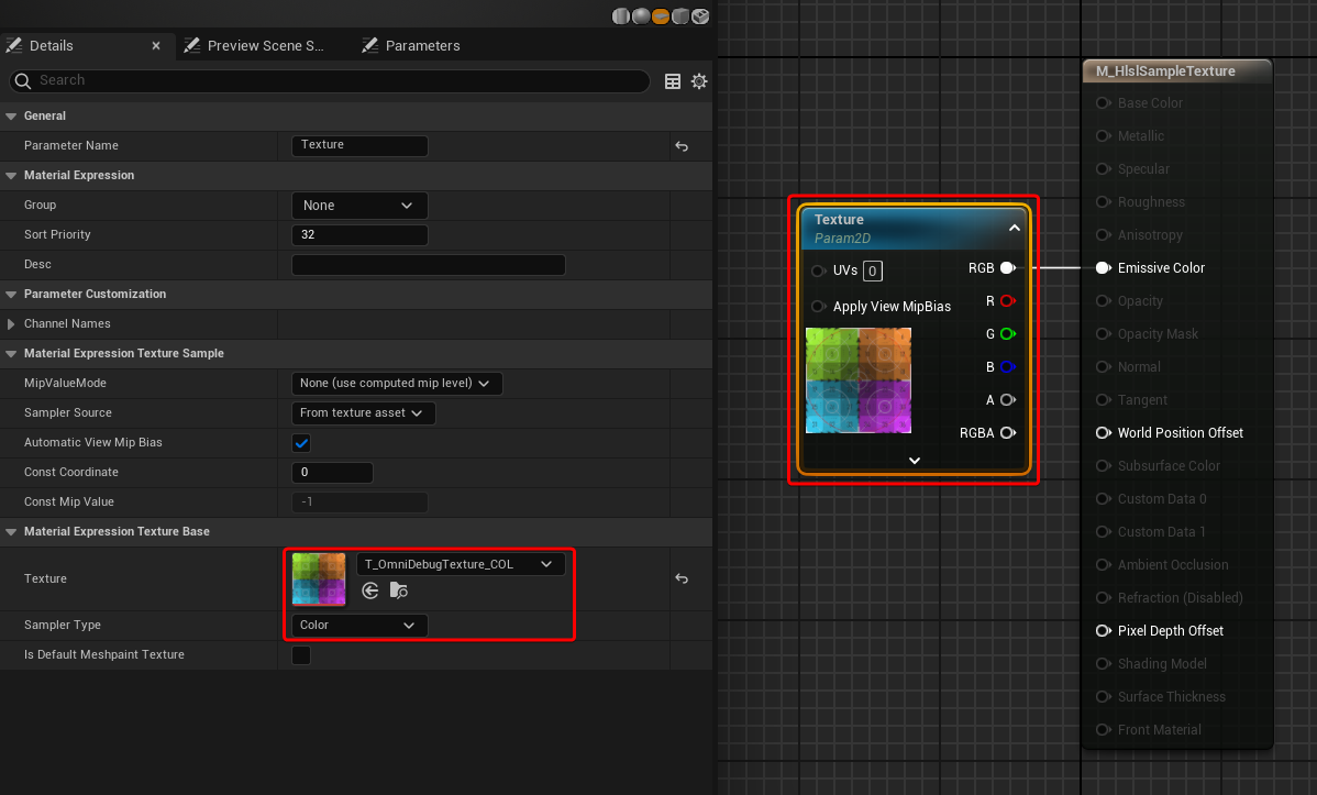
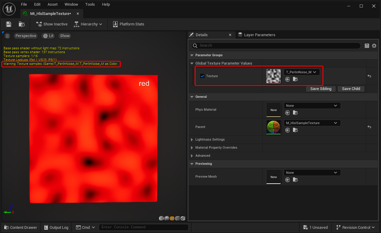
You can see that the material still compiles, but it gives you a warning mentioning that the texture is getting sampled as Color, because it recognises that you might want to sample it as Linear Grayscale, based on the Texture’s Compression Settings.
In fact, we can see that the Emissive result of the material is the texture selected, but in the colour red. This is exactly the same issue encountered earlier when sampling a greyscale Texture without using the Lookup function, and using float4s instead of scalar floats.
When you are working with your own custom code, I believe you can avoid the Lookups altogether, since you probably know already what kind of texture you will be using, what compression setting it has and what output your function should have.
However, I might be wrong, and maybe the Lookups are doing something additional under the hood that I am not aware of.
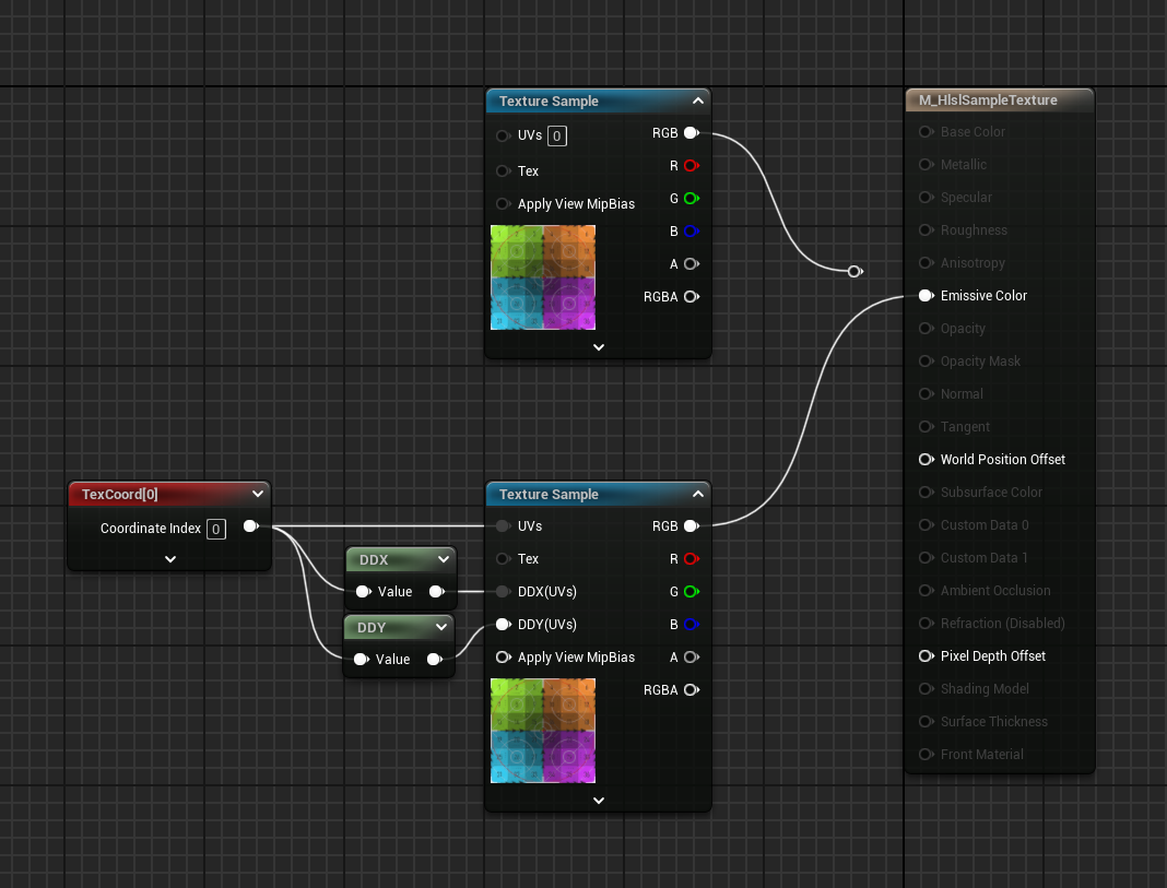
Mipmap
You’ve probably noticed we’ve been using Texture2DSampleBias(), which has been taking View.MaterialTextureMipBias as one of the inputs, and the UV have also been inside a DERIV_BASE_VALUE() function.
I believe these are all necessary to calculate the Mipmap. You can sample the texture without them by using Texture2DSample(), removing the additional input and using the UV variable directly:
float2 myUv = uv;
float4 sampledTex = Texture2DSample(texObject, texObjectSampler, myUv);
return sampledTex;Let’s continue the fun and compare the code of a material that uses a Texture Sample with MipValueMode set to None (use computed mip level) (which is the default value of the node), as well as one with Derivative (explicit derivative to compute mip level) with the relative DDX DDY inputs.
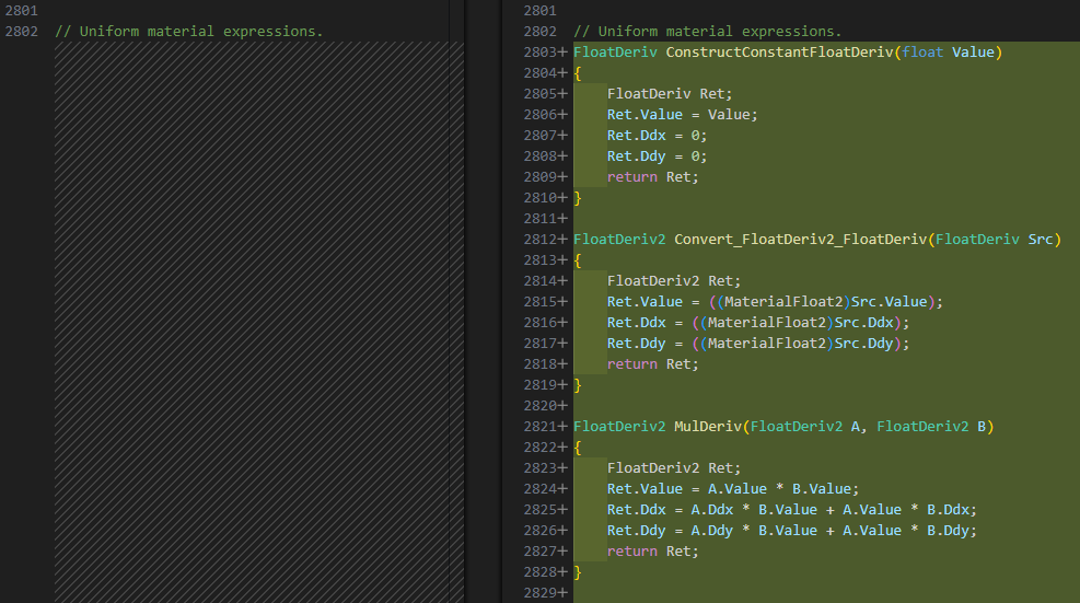
The first thing that changes is the addition of this code under // Unfirom material expressions.:
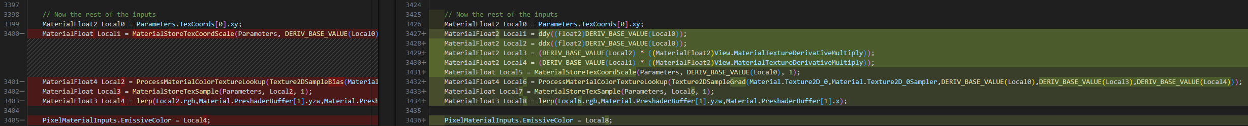
The other changes happen under // Now the rest of the inputs:
It’s very interesting to be able to see all this, a very useful learning resource to find out how things are supposed to be setup so that they can be used to build our own custom systems..
Conclusion
You can, of course, take this further, using the same technique I’ve used throughout the post to compare Unreal compiled HLSL code, play around with the custom node and check what is happening under the hood when various settings are edited.
This investigation started because I wanted to try to do some more complex texture sampling using for loops, which can only be done in a custom node. Sampling a texture is the first step to do so, and I realised I’ve never taken the time to actually look behind the curtains to see how things work. In the past, I’ve always taken snippets from other people online and built on top of them, without questioning it too much.
This was meant to be a short personal exploration, but I ended up constantly finding various things to test, and ended up deciding to share it since I thought it could be useful for someone else.
Hopefully, it will end up becoming a useful resource for anyone that is starting their HLSL adventure in Unreal Engine.
Leave a Reply